

9 января 2021 года на выставке NIO Day 2020 компания Azera Motors официально представила свой первый флагманский седан с интеллектуальным приводом ET7, который является первым серийным седаном Azera и привлек большое внимание представителей отрасли. Главным событием презентации, вероятно, стала технология автономного вождения ET7. Впервые на презентации Azera прямо упомянула, что она сможет автоматически управлять автомобилем в четырех сценариях: на высокой скорости, в городской местности, на парковке и при переключении мощности, и что она сможет создать полный набор возможностей для автоматического вождения.
Конфигурация AQUILA оснащена различными высокопроизводительными датчиками, в том числе высокоточным лазерным радаром сверхдальней дальности, радарами с пятью миллиметровыми волнами, несколькими камерами высокой четкости и множеством других датчиков.
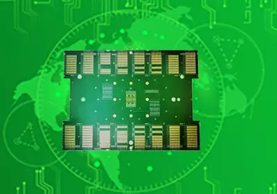
По сравнению с лазерными радарами или камерами, радар миллиметрового диапазона незаменим для реализации различных функций автомобильной системы ADAS благодаря своей надежной работе в неблагоприятных погодных условиях. Материал печатной платы является ключевым материалом и компонентом радара миллиметрового диапазона, а характеристики материала печатной платы определяют характеристики радарных датчиков миллиметрового диапазона. Материал RO3003™ от Rogers, обладающий выдающимися характеристиками, является частью решения для радаров миллиметрового диапазона Azera ET7.
Millimetre wave radar sensors are gradually transitioning from 24GHz to 77GHz, with more forward-facing radars and corner radars using 77GHz solutions. For circuit engineers, choosing the right PCB material is crucial to the millimetre wave radar design. In general, when selecting PCB materials, it is necessary to consider choosing thinner PCB materials,better dielectric constant consistency, smaller dielectric loss, etc. At the same time, it is also necessary to consider the material with the time, temperature, humidity and other external working environment, and have reliable electrical performance and mechanical properties.
Dielectric Constant Consistency
In the millimetre wave radar array antenna design, including different types of transmission lines of the circuit structure size, different transmission lines of the phase difference or time delay, as well as the realization of the antenna spacing control of the various units are determined by the dielectric constant of the material. Changes in the dielectric constant within the same board will result in a certain phase difference between the transceiver and the transmitter of an automotive radar, especially a millimetre-wave automotive radar, which will affect the accuracy of vehicle or speed detection and result in a deviation in its positioning. At the same time, changes in the dielectric constant of different batches of materials will cause differences in different millimetre wave radar systems, affecting the consistency of the system. Therefore, the consistency and stability of the dielectric constant of the PCB material used is of paramount importance. At the same time, the dielectric constant (design Dk) of the final circuit is not only related to the process Dk of the material dielectric, but also closely related to the roughness of the copper foil used, the processing of the circuit, and so on. To ensure the phase consistency of the antenna and the performance consistency of the system, the dielectric constant (design Dk) presented in the circuit is more comprehensive and should be taken into account for the evaluation of the actual radar antenna performance.
Roughness of Copper Cladding
It is well known that the surface roughness of the copper foil used in a material has an effect on the dielectric constant of the circuit. Due to the roughness of the surface of the copper foil, the propagation of electromagnetic waves in the circuit is slowed down. Compared to a very smooth surface of the copper foil, this creates a slow-wave effect, which leads to an increase in the dielectric constant of the circuit. The rougher the surface of the copper foil, the higher the dielectric constant of the circuit, while the smoother the surface of the copper foil, the lower the dielectric constant of the circuit.The smoother the copper foil, the better it is for reducing the effect of copper foil roughness on the design Dk, thus helping to maintain consistent circuit performance. For example, Rogers' RO3003G2™ material uses a smoother copper foil with a smaller filler system to further improve the consistency of the dielectric constant and circuit performance.
Temperature-dependent change in dielectric constant (TCDk)
The dielectric constant of a circuit material changes with temperature, and this temperature-dependent parameter helps engineers to understand the possible changes in the properties of a circuit material. The change in dielectric constant with temperature is usually defined as TCDk, and the smaller the change, the more stable the material (at temperature). The TCDk value of an ideal circuit material will remain a fixed Dk value even if the temperature changes, with a TCDk value of 0ppm/°C. In the real world, however, the TCDk value of an ideal circuit material will remain a fixed Dk value even if the temperature changes. However, in the real world, the Dk value changes as the temperature of the circuit material changes. Only circuit materials with very low TCDk values can be considered as materials with temperature-stable Dk, and usually the absolute value of TCDk is less than 50ppm/°C. When an application requires a circuit with a very low TCDk value, the TCDk value is 0ppm/°C. When an application requires a circuit to withstand a wide range of operating temperatures and to maintain stable performance throughout - such as an automotive radar sensor application, which requires consistently accurate measurements and may operate at different operating temperatures - the TCDk parameter of the material is one of the key parameters to be considered.
A set of experiments was designed to compare the effects of different TCDk values of high TCDk materials with those of RO3003™. A set of 50Ω microstrip line circuits based on the same design was tested to observe the changes in design Dk and phase at different temperatures. The test results are shown in the figure:
The Rogers RO3003™ material has a very small TCDk value, so there is almost no change in Dk and phase angle of the circuit at 77GHz. The high TCDk material has a Dk change of 0.031 and a phase change of 17 degrees at 77 GHz. When millimetre-wave automotive radar sensors using high TCDk materials are applied in different temperature environments, such high Dk and phase variations will seriously affect the consistency of the system.
Гигроскопичность материалов
Преимущество автомобильных радарных датчиков миллиметрового диапазона перед другими типами датчиков заключается в том, что они могут работать в режиме 24/7 при любых неблагоприятных погодных условиях. Таким образом, в окружающей среде меняется не только температура, но и влажность. Инженеры-проектировщики при выборе материалов для схем часто игнорируют влагопоглощение материала, но на самом деле влагопоглощение материала также имеет решающее значение для производительности схемы и согласованности системы. Меньшая гигроскопичность материала уменьшает изменение диэлектрической проницаемости и потери в цепи, тем самым сохраняя практически идентичные характеристики схемы и гарантируя, что расположение радарных датчиков не будет отклоняться.
Низкое влагопоглощение материала Rogers RO3003™ - одна из ключевых причин, по которой он широко используется в автомобильных радарах миллиметрового диапазона частот 77 ГГц.

Влияние процесса производства печатных плат
После завершения проектирования схемы ее необходимо включить в схему антенны радара.Коэффициент усиления антенны радара миллиметрового диапазона зависит от вносимых в схему потерь. Различная обработка поверхности схемы будет по-разному влиять на схему.Чистота поверхности печатной платы имеет важное значение для обработки печатных плат, не только для обеспечения гладкой и пригодной для пайки поверхности, но и для защиты медных проводников печатной платы. Однако большинство материалов для обработки поверхности печатных плат обладают меньшей электропроводностью, чем медная фольга. Чем ниже электропроводность, тем выше потери в проводнике и, следовательно, тем выше вносимые потери в цепи, особенно в цепях миллиметрового диапазона волн. Чтобы лучше понять влияние обработки поверхности на показатели потерь, для сравнения потерь было обработано несколько комплектов линий электропередачи, изготовленных из одного и того же материала, но с различной обработкой поверхности.
Уникальные преимущества радарных датчиков миллиметрового диапазона частот 77 ГГц делают их незаменимыми компонентами для самоуправляемых автомобилей. Материалы печатных плат определяют характеристики антенн радиолокационных датчиков миллиметрового диапазона, и выбор материалов со стабильными диэлектрическими постоянными и малыми потерями имеет решающее значение для успешного проектирования радиолокационных датчиков миллиметрового диапазона. Для достижения стабильной и согласованной работы радиолокационного датчика необходимо учитывать такие параметры, как используемая в материале медная фольга и шероховатость ее поверхности, изменение диэлектрической проницаемости в зависимости от температуры и гигроскопичность материала. В то же время ряд факторов во время обработки также влияют на работу радарного датчика. В целом, хорошая связь с поставщиками материалов и инженерами-технологами на начальном этапе проектирования и в процессе обработки может улучшить стабильность работы радара с частотой 77 ГГц, увеличить производительность и снизить стоимость.